

Building a 3D Engine in Perl, Part 3
This article is the third in a series aimed at building a full 3D engine in Perl. The first article started with basic program structure and worked up to displaying a simple depth-buffered scene in an OpenGL window. The second article followed with a discussion of time, view animation, SDL events, keyboard handling, and a nice chunk of refactoring.
Editor’s note: see also the next article in the series, profiling your application.
Later in this article, I’ll discuss movement of the view position, continue the refactoring work by cleaning up draw_view, and begin to improve the look of our scene using OpenGL lighting and materials. Before I cover that, your feedback to the previous articles has included a couple of common requests: screenshots and help with porting issues. If you’re having problems running SDL_Perl and the sample code from these articles on your system, or might be able to help the Mac OS X and Win32 readers, take a look at the next section. Otherwise, skip down to the Screenshots section, where the main article begins.
Known Porting Issues
General
Some versions of SDL_Perl require that the program load SDL::Constants to recognize SDL_QUIT and other constants. As this change should be transparent to other users, I have merged that into the latest version of the sample code, retroactive to the first use of an SDL constant.
FreeBSD
See the suggestions at the beginning of the second article.
Mac OS X
I spent some time research the porting issues on Mac OS X but am as yet unable to figure out a simple procedure for building SDL_Perl from scratch. Recent emails on the sdl-devel mailing list seem to indicate that Mac OS X builds for recent SDL_Perl sources are problematic right now, but older releases seem to be even worse. There have been some packaging attempts in the past, but none that I have found so far install a fully configured set of SDL_Perl libraries into the system perl. I’m no Mac porting expert, so I appreciate any help on this; please post a comment in this month’s article discussion if you have a suggestion or solution.
Slackware
According to comments by Federico (ironfede) in last month’s article discussion, Slackware ships with a version of SDL_Perl that requires SDL::Constants. This is not an issue for the current version of the sample code, which I fixed as mentioned above in the General issues paragraph.
Win32
Win32 porting went as did Mac OS X porting. I was quite excited when chromatic pointed me to some old Win32 PPM packages, but sadly they don’t include a working version of SDL::OpenGL. Building manually was “interesting” at best, as I have no access to a Microsoft compiler and precious little experience using gcc under Win32. As with the Mac folks, I appreciate any help from the readers. Please post a comment in this month’s article discussion if you have a suggestion or solution for your fellows.
Screenshots
Thankfully, screenshots are much easier to handle than porting issues. I’d like the user to be able to take a screenshot whenever desired. The obvious way to accomplish that is to bind the screenshot action to a key; I chose function key F4 at random. First I added it to the bind hash:
        bind   => {
            escape => 'quit',
            f4     => 'screenshot',
            left   => '+yaw_left',
            right  => '+yaw_right',
            tab    => '+look_behind',
        }
The new key must have an action routine, so I altered that lookup hash as well:
    $self->{lookup}{command_action} = {
          quit         => \&action_quit,
          screenshot   => \&action_screenshot,
        '+yaw_left'    => \&action_move,
        '+yaw_right'   => \&action_move,
        '+look_behind' => \&action_move,
    };
I need to wait until drawing completes for the entire scene before I can take a snapshot, but event processing happens before drawing begins. To work around this, I set a state variable marking that the user has requested a screenshot, rather than perform the screenshot immediately:
sub action_screenshot
{
    my $self = shift;

    $self->{state}{need_screenshot} = 1;
}
The code checks this state variable in a new line at the end of end_frame, after the drawing has completed and it has synced the screen with the image written into OpenGL’s color buffer:
sub end_frame
{
    my $self = shift;

    $self->{resource}{sdl_app}->sync;
    $self->screenshot if $self->{state}{need_screenshot};
}
The screenshot routine is surprisingly short but dense:
sub screenshot
{
    my $self = shift;

    my $file = 'screenshot.bmp';
    my $w    = $self->{conf}{width};
    my $h    = $self->{conf}{height};

    glReadBuffer(GL_FRONT);
    my $data = glReadPixels(0, 0, $w, $h, GL_BGR,
                            GL_UNSIGNED_BYTE);
    SDL::OpenGL::SaveBMP($file, $w, $h, 24, $data);

    $self->{state}{need_screenshot} = 0;
}
The routine starts by specifying a filename for the screenshot and gathering the width and height of the screen. The real work begins with the call to glReadBuffer. Depending on the OpenGL driver, the hardware, and a number of advanced settings, OpenGL may have provided several color buffers in which to draw and read images. In fact, the default behavior on most systems is to draw onto one buffer, known as the back buffer, and display a separate buffer, known as the front buffer. After completing the drawing for each frame, the SDL::App::sync call moves the image from the back buffer to the front buffer so the user can see it. Behind the scenes, OpenGL generally handles this in one of two different ways, depending on the underlying implementation. Software OpenGL implementations, such as Mesa, copy the data from the back buffer to the front buffer. Hardware-accelerated systems can swap internal pointers so that the back buffer becomes the front buffer and vice versa. As you can imagine, this is much faster.
This extra work brings a great benefit. Without double buffering, as soon as one frame completes, the next frame immediately clears the screen to black and starts drawing again from scratch. Depending on the relative speed difference between the user’s monitor and the application, this would probably appear to the user as a flickering, dark, perpetually half-drawn scene. With double buffering, this problem is almost gone. The front buffer shows a solid stable image while all of the drawing is done on the back buffer. Once the drawing completes, it takes at most a few milliseconds to sync up and start displaying the new frame. To the human eye, the animation appears solid, bright, and (hopefully) smooth.
In this case, I want to make sure that I take a screenshot of exactly the same image the user sees, so I tell OpenGL that I want to read the image in the front buffer (GL_FRONT).
At this point, it’s safe to read the image data into a Perl buffer in the proper format. The first four arguments to glReadPixels specify the lower-left corner and size of the sub-image to read. The next two arguments together tell OpenGL what format I would like for the data. I specify that I want to read the entire window and that I want the data in the correct format for a BMP file–one unsigned byte for each of the red, green, and blue color channels for each pixel, but in reverse order.
Once I have the data from OpenGL I use the SDL_Perl utility routine SaveBMP to save the image into a file. The arguments are the filename, image width, image height, color depth (24 bits per pixel), and data buffer. Finally, the routine resets the need_screenshot state flag and returns.
At this point you should be able to take a screenshot each time you press the F4 key. Of course, I’d like to show several screenshots during this article as the code progresses. The current code overwrites the previous screenshot file every time I request a new one. Because I number each runnable version of the code, I used a quick workaround resulting in a different screenshot filename for each code step. I first load one of the core Perl modules to strip directories from a path:
use File::Basename;
Then I use the filename of the script itself as part of my screenshot filename:
my $file = basename($0) . '.bmp';
This may be all you need for your application, or you may want to add some code to number each file uniquely. This code is enough to fix my problem, so I’ve left the more powerful version as an exercise for the reader.
Here then is the first screenshot:
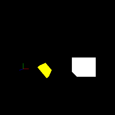
The observant reader will notice that this image is not a BMP file; it’s a PNG image, which is both much smaller than a BMP and more friendly to web standards. There are many tools available that can perform this conversion. Any good image editor can do it. In this case that’s overkill–I instead used the convert program from the ImageMagick suite of utilities:
convert step042.bmp step042.png
Moving the Viewpoint
That view is more than a tad overplayed. The user can’t even move the viewpoint to see the back or sides of the scene. It’s time to change that. I started by defining some new key bindings:
        bind   => {
            escape => 'quit',
            f4     => 'screenshot',
            a      => '+move_left',
            d      => '+move_right',
            w      => '+move_forward',
            s      => '+move_back',
            left   => '+yaw_left',
            right  => '+yaw_right',
            tab    => '+look_behind',
        }
I then updated the command_action lookup hash to handle these as movement keys:
    $self->{lookup}{command_action} = {
          quit          => \&action_quit,
          screenshot    => \&action_screenshot,
        '+move_left'    => \&action_move,
        '+move_right'   => \&action_move,
        '+move_forward' => \&action_move,
        '+move_back'    => \&action_move,
        '+yaw_left'     => \&action_move,
        '+yaw_right'    => \&action_move,
        '+look_behind'  => \&action_move,
    };
init_view needs to initialize two more velocity components and matching deltas:
    $self->{world}{view} = {
        position    => [6, 2, 10],
        orientation => [0, 0, 1, 0],
        d_yaw       => 0,
        v_yaw       => 0,
        v_forward   => 0,
        v_right     => 0,
        dv_yaw      => 0,
        dv_forward  => 0,
        dv_right    => 0,
    };
action_move needs a new movement speed to match the existing yaw speed and some additions to %move_update:
    my $speed_move       = 5;
    my %move_update      = (
        '+yaw_left'     => [dv_yaw     =>  $speed_yaw ],
        '+yaw_right'    => [dv_yaw     => -$speed_yaw ],
        '+move_right'   => [dv_right   =>  $speed_move],
        '+move_left'    => [dv_right   => -$speed_move],
        '+move_forward' => [dv_forward =>  $speed_move],
        '+move_back'    => [dv_forward => -$speed_move],
        '+look_behind'  => [d_yaw      =>  180        ],
    );
So far, the changes are mostly hash updates instead of procedural code; that’s a good sign that the existing code design has some more life left. When conceptually simple changes require significant code modification, especially special cases or repetitive blocks of code, it’s time to look for a refactoring opportunity. Thankfully, these changes are in initialization and configuration rather than special cases.
One routine that requires a good bit of new code is update_view. I added these lines to the end:
    $view->{v_right}        += $view->{dv_right};
    $view->{dv_right}        = 0;
    $view->{v_forward}      += $view->{dv_forward};
    $view->{dv_forward}      = 0;

    my $vx                   =  $view->{v_right};
    my $vz                   = -$view->{v_forward};
    $view->{position}[0]    += $vx * $d_time;
    $view->{position}[2]    += $vz * $d_time;
That routine is beginning to look a bit repetitious and has several copies of very similar lines of code, so it goes on the list of places to refactor in the future. There are not yet enough cases to make the best solution obvious, so I’ll hold off for a bit.
The new code starts by applying the new velocity deltas in the same way that it updates v_yaw earlier in the routine. It converts the right and forward velocities to velocities along the world axes by noting that the view starts out with “forward” parallel to the negative Z axis and “right” parallel to the positive X axis. It then multiplies the X and Z velocities by the time delta to arrive at a position change, which it adds into the current view position.
This version of the code works fine as long as the user doesn’t rotate the view. When the view rotates, “forward” and “right” don’t match the new view directions. They still point down the -Z and +X axes respectively, which can prove very disorienting for high rotations. The solution is a bit of trigonometry. The idea is treat the initial X and Z velocities as components of the total velocity vector, and rotate that vector through the same angle that the user rotated the view:
    my $vx                   =  $view->{v_right};
    my $vz                   = -$view->{v_forward};
    my $angle                = $view->{orientation}[0];
    ($vx, $vz)               = rotate_xz($angle, $vx, $vz);
    $view->{position}[0]    += $vx * $d_time;
    $view->{position}[2]    += $vz * $d_time;
The two middle lines are the new ones. They call rotate_xz to do the vector rotation work and then set $vx and $vz to the returned components of the rotated velocity vector. rotate_xz is:
sub rotate_xz
{
    my ($angle, $x, $z) = @_;

    my $radians = $angle * PI / 180;
    my $cos     = cos($radians);
    my $sin     = sin($radians);
    my $rot_x   =  $cos * $x + $sin * $z;
    my $rot_z   = -$sin * $x + $cos * $z;

    return ($rot_x, $rot_z);
}
After converting the angle from degrees to radians, the code calculates and saves the sine and cosine of the angle. It then calculates the rotated velocity components given the original unrotated components. Finally, it returns the rotated components to the caller.
I’ll skip the derivation here (you’re welcome), but if you’re curious about how and why this calculation performs a rotation, there are numerous books that explain the wonders of vector mathematics in amazing detail. O’Reilly’s Physics for Game Developers, by David M. Bourg, includes a high-level discussion of rotation. Charles River Media’s Mathematics for 3D Game Programming & Computer Graphics, by Eric Lengyel, includes a deeper discussion though I, for one, have college math flashbacks every time I read it. Speaking of which, any college textbook on linear algebra should include as much detail as you desire.
This code requires a definition for PI, provided by the following line near the top of the program, right after requesting warnings from Perl:
use constant PI => 4 * atan2(1, 1);
The constant module evaluates possibly complex calculations during the compile phase and then converts them into constants at runtime. The above calculation takes advantage of a standard trig identity to derive a value for PI accurate to as many digits as the system can deliver.
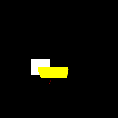
update_view now does the right thing, no matter what angle the view is facing. It doesn’t take long to find a more interesting view:
Let There Be Lighting!
Okay, so maybe that’s not much more interesting, admittedly. This scene needs a little mood lighting instead of the flat colors I’ve used so far (especially because they make it hard to see the shape of each object clearly). As a first step, I turned on OpenGL’s lighting system with a new line at the end of prep_frame:
glEnable(GL_LIGHTING);
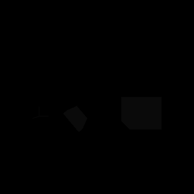
Far from lighting the scene, the view is now almost black. If you look very carefully and your monitor and room lighting are forgiving, you should be able to just make out the objects, which are very dark gray on the black background. In order to see anything, I must enable both GL_LIGHTING and one or more lights to provide light to the scene. Without a light, the objects are dark gray instead of true black because OpenGL, by default, applies a very small amount of light to the entire scene, known as ambient light. To show the objects more brightly, I turned on the first OpenGL light with another new line at the end of prep_frame:
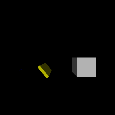
glEnable(GL_LIGHT0);

Now the objects are brighter, but they’re still just gray. When calculating colors with lighting enabled, OpenGL uses a completely different set of parameters from the colors used when lighting is disabled. Together these new parameters make up a material. Complex interactions between the parameters that make up a material can result in very interesting color effects, but in this case, I’m not trying to create a complex effect. I want my objects to have their old colors back without worrying about the full complexity that materials provide. Thankfully, OpenGL provides a way to state that the current material should default to the current color. To do this, I add yet another line to the end of prep_frame:
glEnable(GL_COLOR_MATERIAL);

At this point, the objects once again have color, but each of the faces is still the same shade rather than appearing to be lit by a single light source somewhere. The problem is that OpenGL does not know whether each face points toward or away from the light and, if so, by how much. The angle between the face and the light determines how much light falls on the surface and, therefore, how bright it should appear. It is possible to calculate the angle of each face in my scene from the location of its vertices, but this is not always the right thing to do (especially when dealing with curved surfaces), so OpenGL does not calculate this internally. Instead, the program needs to do the direction calculations and tell OpenGL the result, known as the normal vector.
Luckily, in draw_cube the faces align with the coordinate axes so that each face points down one of them (positive or negative X, Y, or Z). I don’t have to do any calculation here, just tell OpenGL which normal vector to associate with each face:
sub draw_cube
{
    # A simple cube
    my @indices = qw( 4 5 6 7   1 2 6 5   0 1 5 4
                      0 3 2 1   0 4 7 3   2 3 7 6 );
    my @vertices = ([-1, -1, -1], [ 1, -1, -1],
                    [ 1,  1, -1], [-1,  1, -1],
                    [-1, -1,  1], [ 1, -1,  1],
                    [ 1,  1,  1], [-1,  1,  1]);
    my @normals = ([0, 0,  1], [ 1, 0, 0], [0, -1, 0],
                   [0, 0, -1], [-1, 0, 0], [0,  1, 0]);

    glBegin(GL_QUADS);

    foreach my $face (0 .. 5) {
        my $normal = $normals[$face];
        glNormal(@$normal);

        foreach my $vertex (0 .. 3) {
            my $index  = $indices[4 * $face + $vertex];
            my $coords = $vertices[$index];
            glVertex(@$coords);
        }
    }
    glEnd;
}
The new lines are the definition of the @normals array and the two lines at the top of the $face loop that select the correct normal for each face and pass it to OpenGL using glNormal.
The boxes are now shaded reasonably and it’s clear that the light is coming from somewhere behind the viewer; the front faces are brighter than the sides. Unfortunately, the axes are now dark again:
I did not specify any normal for the axis lines because the concept doesn’t make a whole lot of sense for lines or points. However, with lighting enabled, OpenGL needs a set of normals for every lit object, so it goes back to the current state and uses the most recently defined normal. For the very first frame this is the default normal, which happens to point towards the default first light, but for succeeding frames it will be the last normal set in draw_cube. The latter definitely does not point toward the light, and the axes end up dark.
I’d rather the axis lines didn’t take part in lighting calculations at all and kept their original bright colors, regardless of any lighting (or lack thereof) in the scene. To do this, I removed the line that enables GL_LIGHTING in prep_frame and inserted two new lines near the top of draw_view:
sub draw_view
{
    glDisable(GL_LIGHTING);

    draw_axes();

    glEnable(GL_LIGHTING);
Now lighting is off before drawing the axis lines and back on afterward. The axis lines have bright colors again, but rotating the view exposes a new problem. When the view rotates, the direction of the light changes as well:
Because of the way that OpenGL calculates light position and direction, any lights defined before the view is set are fixed to the viewer like the light on a miner’s helmet. To fix a light relative to the simulated world, define the light instead after setting the view. I removed the line enabling GL_LIGHT0 in prep_frame and moved it to the new routine set_world_lights:
sub set_world_lights
{
    glEnable(GL_LIGHT0);
}
I then updated draw_frame to call the new routine after setting the view:
sub draw_frame
{
    my $self = shift;

    $self->set_projection_3d;
    $self->set_view_3d;
    $self->set_world_lights;
    $self->draw_view;
}
Unfortunately, this doesn’t work. OpenGL only updates its internal state with the light’s position and direction when they change explicitly, not when the light is enabled or disabled. I’ve never set the light’s parameters explicitly, so the original default still stands. This issue is easy to fix with another line in set_world_lights:
sub set_world_lights
{
    glLight(GL_LIGHT0, GL_POSITION, 0.0, 0.0, 1.0, 0.0);

    glEnable(GL_LIGHT0);
}
In one of the few OpenGL interface decisions that actively annoys me, the new line sets the direction of the light, not its position. OpenGL defines all lights as one of two types: directional or positional. OpenGL assumes directional lights are very far away so that anywhere in the scene the direction from the light to each object is effectively the same. Positional lights are nearer and OpenGL must calculate the direction from the light to every vertex of every object in the scene independently. As you can imagine, this is much slower, but produces more interesting lighting effects.
The key to choosing between these two types is the last parameter of the glLight call above. If this parameter is 0, the light is directional and the other three coordinates specify the direction from which the light comes. In this case, I’ve specified that the light should come from the +Z direction. If the last parameter is 1, then OpenGL makes the light positional and uses the other three coordinates to set the light’s position within the scene. For now, I’ll skip the gory details of what happens when a value other than 0 or 1 is used, but in short, the light will be positional and extra calculations determine the actual position used. Most of the time it’s best to ignore that case.
You may wonder why I explicitly specified 0.0 and 1.0 instead of 0 and 1. This is a workaround for a bug in glLight in some versions of SDL_Perl when it is presented with integer arguments instead of floating-point arguments.
With this line added, the light now stays fixed in the world, even when the user moves and rotates the view:
A Lantern
Of course, sometimes a light connected to the viewer is exactly the intention. For example, perhaps the desired effect is for the player to hold a lantern or flashlight to light dark places. Both of these are localized light sources that light nearby objects quite a bit, but distant objects only a little. The primary difference between them is that a flashlight and certain types of lanterns cast light primarily in one direction, often in a cone. Most lanterns, torches, and similar light sources cast light in all directions (barring shadows from handles, fuel tins, and the like).
Non-directed light is a little simpler to implement, so I’ll start with lantern light. I wanted the light rooted at the viewer’s position, so I defined the light before setting the view:
sub draw_frame
{
    my $self = shift;

    $self->set_projection_3d;
    $self->set_eye_lights;
    $self->set_view_3d;
    $self->set_world_lights;
    $self->draw_view;
}
I refer to viewer-fixed lights as eye lights because OpenGL refers to the coordinate system it uses for lights as eye coordinates, and a light defined this way as maintaining a particular position “relative to the eye.” Here’s set_eye_lights:
sub set_eye_lights
{
    glLight(GL_LIGHT1, GL_POSITION, 0.0, 0.0, 1.0, 0.0);

    glEnable(GL_LIGHT1);
}
Here I set the second light exactly the same way I set the first. Note that it doesn’t matter that I actually define the second light in my program before the first. Each OpenGL light is independently numbered and always keeps the same number, rather than acting like a stack or queue numbered by order of use.
Sadly, the new code doesn’t seem to have any effect at all. In reality, there really is a new light shining on the scene–unlike GL_LIGHT0, which defaults to shining bright white, all of the other lights default to black and provide no new light to the scene. The solution is to set another parameter of the light:
sub set_eye_lights
{
    glLight(GL_LIGHT1, GL_POSITION, 0.0, 0.0, 1.0, 0.0);
    glLight(GL_LIGHT1, GL_DIFFUSE,  1.0, 1.0, 1.0, 1.0);

    glEnable(GL_LIGHT1);
}
The front faces of each object should appear considerably brighter. Moving around the scene shows that the eye light brightens a surface only dimly lit by the world light:
If you watch carefully, however, you’ll notice that the lighting varies by the view rotation–not position. I defined the light as directional with the light coming from behind the viewer, rather than positional, with the light coming from the viewer directly. I hinted at the fix earlier–changing the GL_POSITION parameter as follows:
glLight(GL_LIGHT1, GL_POSITION, 0.0, 0.0, 0.0, 1.0);
The light now comes from (0, 0, 0) in eye coordinates, right at the viewpoint. Moving around and rotating shows that this version has the intended effect.
The simulated lantern still shines as brightly on far-away objects as it does on near ones. A real lantern’s light falls off rapidly with distance from the lantern. OpenGL can do this with another setting:
sub set_eye_lights
{
    glLight(GL_LIGHT1, GL_POSITION, 0.0, 0.0, 0.0, 1.0);
    glLight(GL_LIGHT1, GL_DIFFUSE,  1.0, 1.0, 1.0, 1.0);
    glLight(GL_LIGHT1, GL_LINEAR_ATTENUATION, 0.5);

    glEnable(GL_LIGHT1);
}
This case tells OpenGL to include a dimming term in its equations proportional to the distance between the light and the object. Physics-minded readers will point out that physically accurate dimming is proportional to the square of the distance, and OpenGL does allow this using GL_QUADRATIC_ATTENUATION. However, a host of factors (including the lighting equations that OpenGL uses and the non-linear effects of the graphics hardware, monitor, and human eye) make this more accurate dimming look rather odd. Linear dimming turns out to look better in many cases, so that’s what I used here. It is also possible to combine different dimming types, so that the dimming appears linear for nearby objects and quadratic for distant ones, which you may find a better tradeoff. The 0.5 setting tells OpenGL how strong the linear dimming effect should be for my scene.
Moving around the scene, you should be able to see the relatively subtle dimming effect in action. Don’t be afraid to leave it subtle instead of turning the dimming effect way up. Some moods call for striking lighting effects, while others call for lighting effects that the viewer notices only subconsciously. In some visualization applications, lighting subtlety is a great virtue, allowing the human visual system’s amazing processing power to come to grips with a complex scene without being overwhelmed.
A Flashlight
I really happen to like the way a flashlight casts its cone of light, so I converted the omnidirectional light of the lantern to a directed cone. OpenGL refers to this type of light as a spotlight and includes several light parameters to define them. The first change is a new setting in set_eye_lights:
glLight(GL_LIGHT1, GL_SPOT_CUTOFF, 15.0);
This sets the angle between the center of the light beam and the edges of the cone. OpenGL accepts either 180 degrees (omnidirectional) or any value between 0 and 90 degrees (from a laser beam to a hemisphere of light). In this case, I chose a centerline-to-edge angle of 15 degrees, making a nice 30-degree-wide cone of light.
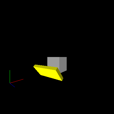
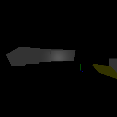
This change indeed limits the cone of light, but also reveals an ugly artifact. Move to a point just in front of the left front corner of the white cube and rotate the view to pan the light across the yellow box. You’ll see the light jump nastily from corner to corner, even disappearing entirely in between. Even when a corner is lit, the shape of the light is not very conelike:
OpenGL’s standard lighting model only performs the lighting calculations at each vertex, interpolating the results in between. For models that have many small faces and a resulting high density of vertices, this works relatively well. It breaks down nastily in scenes containing objects with large faces and few vertices, especially when a positional light is close to an object. Spotlights make the problem even more apparent, as they can easily shine between two vertices without lighting either of them; the polygon then appears uniformly dark.
Ode to Rush
Advanced OpenGL functionality paired with recent hardware can solve this problem with per-pixel lighting calculations. Older hardware can fake it with light maps and similar tricks. Rather than using advanced functionality, I’ll use a simpler method for improving the lighting, known as subdivisions. (Those of you scratching your heads over the Rush reference can now breathe a collective sigh of relief.) Subdivisions have their own problems, as I’ll show later, but those issues explain a lot about the design of graphics APIs, so they’re worth a look.
As the name implies, the basic idea is to subdivide each face into many smaller faces, each with its own set of vertices. For curved objects such as spheres and cylinders, this is essential so that nearby objects appear to curve smoothly. For objects with large flat faces, such as boxes and pyramids, this merely has the side effect of forcing the per-vertex lighting calculations to be done many times across each face.
Before I can use subdivided faces, I need to prepare by refactoring draw_cube:
sub draw_cube
{
    # A simple cube
    my @indices = qw( 4 5 6 7   1 2 6 5   0 1 5 4
                      0 3 2 1   0 4 7 3   2 3 7 6 );
    my @vertices = ([-1, -1, -1], [ 1, -1, -1],
                    [ 1,  1, -1], [-1,  1, -1],
                    [-1, -1,  1], [ 1, -1,  1],
                    [ 1,  1,  1], [-1,  1,  1]);
    my @normals = ([0, 0,  1], [ 1, 0, 0], [0, -1, 0],
                   [0, 0, -1], [-1, 0, 0], [0,  1, 0]);

    foreach my $face (0 .. 5) {
        my $normal = $normals[$face];
        my @corners;

        foreach my $vertex (0 .. 3) {
            my $index  = $indices[4 * $face + $vertex];
            my $coords = $vertices[$index];
            push @corners, $coords;
        }
        draw_quad_face(normal    => $normal,
                       corners   => \@corners);
    }
}
Instead of performing the OpenGL calls directly in draw_cube, it now calls draw_quad_face. For each large face it creates a new @corners array filled with the vertex coordinates of the corners of that face. It then passes that array and the face normal to draw_quad_face, defined as follows:
sub draw_quad_face
{
    my %args    = @_;
    my $normal  = $args{normal};
    my $corners = $args{corners};

    glBegin(GL_QUADS);
    glNormal(@$normal);

    foreach my $coords (@$corners) {
        glVertex(@$coords);
    }
    glEnd;
}
This function performs exactly the OpenGL operations that draw_cube used to do. I’ve also used a different argument-passing style for this routine than I have previously. In this case, I pass named arguments because I know that I will add at least one more argument very soon and that there’s a pretty good chance I’ll want to add more later. When the arguments to a routine are likely to change over time, and especially when callers might want to specify only a few arguments and allow the rest to take on reasonable defaults, named arguments are usually a better choice. The arguments can either be a hashref or a list stuffed into a hash. This time, I chose the latter method.
After refactoring comes testing, and a quick run showed that everything worked as expected. Safe in that knowledge, I rewrote draw_quad_face to subdivide each face:
sub draw_quad_face
{
    my %args    = @_;
    my $normal  = $args{normal};
    my $corners = $args{corners};
    my $div     = $args{divisions} || 10;
    my ($a, $b, $c, $d) = @$corners;

    # NOTE: ASSUMES FACE IS A PARALLELOGRAM

    my $s_ab = calc_vector_step($a, $b, $div);
    my $s_ad = calc_vector_step($a, $d, $div);

    glNormal(@$normal);
    for my $strip (0 .. $div - 1) {
        my @v = ($a->[0] + $strip * $s_ab->[0],
                 $a->[1] + $strip * $s_ab->[1],
                 $a->[2] + $strip * $s_ab->[2]);

        glBegin(GL_QUAD_STRIP);
        for my $quad (0 .. $div) {
            glVertex(@v);
            glVertex($v[0] + $s_ab->[0],
                     $v[1] + $s_ab->[1],
                     $v[2] + $s_ab->[2]);

            $v[0] += $s_ad->[0];
            $v[1] += $s_ad->[1];
            $v[2] += $s_ad->[2];
        }
        glEnd;
    }
}
The new routine starts by adding the new optional argument divisions, which defaults to 10. This specifies how many subdivisions the face should have both “down” and “across”; the actual number of sub-faces is the square of this number. For the default 10 divisions, that comes to 100 sub-faces for each large face, so each cube has 600 sub-faces.
The next line labels the corners in counterclockwise order. This puts corner A diagonally across from corner C, with B on one side and D on the other.
As the comment on the next line indicates, I’ve simplified the math considerably by assuming that the face is at least a parallelogram. With this simplification, I can calculate the steps for one division along sides AB and AD and use these steps to position every sub-face across the entire large face.
I can’t just calculate the step as a simple distance to move, because I have no idea which direction each edge is pointing and wouldn’t know which way to move for each step. Instead, I calculate the vector difference between the vertices at each end of the edge and divide that by the number of divisions. The code does the same calculation twice, so I’ve extracted it into a separate routine:
sub calc_vector_step
{
    my ($v1, $v2, $div) = @_;

    return [($v2->[0] - $v1->[0]) / $div,
            ($v2->[1] - $v1->[1]) / $div,
            ($v2->[2] - $v1->[2]) / $div];
}
Returning to draw_quad_face, it stores the vector steps in $s_ab (the step along the AB side) and $s_ad (the step along the AD side). Next it sets the current normal, which for a flat face remains the same across its entirety.
Finally, I can begin to define the sub-faces themselves. I’ve taken advantage of the OpenGL quad strip primitive to draw the sub-faces as a series of parallel strips extending from the AB edge to the CD edge. For each strip, I first need to calculate the location of its starting vertex. I know this is on the AB edge, so the code starts at A and adds an AB step for each completed strip. For the first strip, this puts the starting vertex at A. For the last strip, the starting vertex will be one step (one strip width) away from B. It initializes the current vertex @v with the starting vertex and will keep it updated as it moves along each strip.
It then begins a strip of quads with glBegin(GL_QUAD_STRIP). To define the strip, I’ve specified the locations of each pair of vertices across from each other along its length. For each pair, it uses the current vertex and a calculated vertex one step further along the AB direction. The code then moves the current vertex one step along the length of the strip (the AD direction). Once the strip is complete, it ends it with glEnd and loops again for the next strip.
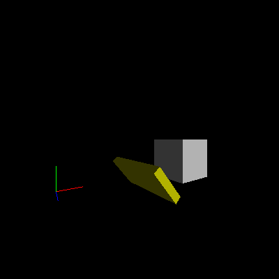
All of this complexity makes quite a visual difference:
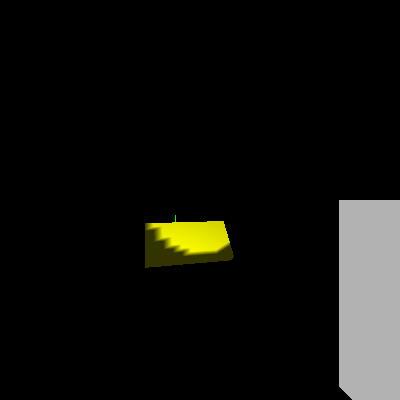
It’s clear that the light has a definite shape to it, but the lighting is so jagged that it’s distracting. One way to fix this is to increase the number of divisions, making smaller sub-faces. This requires a simple addition to the draw_quad_face call in draw_cube:
        draw_quad_face(normal    => $normal,
                       corners   => \@corners,
                       divisions => 30);
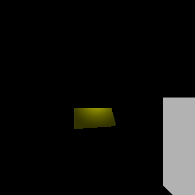
The result is quite a bit less jagged:
Unfortunately, the jaggies are smaller but still obviously there–and the closer the viewer is to an object the bigger they appear. There are also nine times as many sub-faces to draw (30/10 squared) and the program now runs considerably slower. If you’re lucky enough to have a recent system with fast video hardware and don’t notice the slowdown, use 100 or so for the number of divisions. You’ll probably see it.
Softening the Edges
Clearly, increasing the number of subdivisions only goes so far to improve the rendering, while simultaneously costing dearly in performance. I’ll try a different tack and go back to what I know about a flashlight. Most flashlights cast a beam that is brighter in the center than at the edge. (Some have a dark circle in the very center, but I’m ignoring that for now.) I can take advantage of this to create a more accurate image and also soften the large jaggies considerably. First, I backed out my change to the draw_quad_face call:
        draw_quad_face(normal    => $normal,
                       corners   => \@corners);
Then I changed one spotlight parameter for the flashlight in set_eye_lights and added another:
    glLight(GL_LIGHT1, GL_SPOT_CUTOFF,   30.0);
    glLight(GL_LIGHT1, GL_SPOT_EXPONENT, 80.0);
With the change to GL_SPOT_CUTOFF, I’ve widened the beam to twice its original angle. At the same time, I’ve told OpenGL to make it quite a bit dimmer at the edges using GL_SPOT_EXPONENT, hopefully hiding any jaggies. The new parameter has a somewhat confusing name that refers to the details of the equation that determines the strength of the off-center dimming effect. In a theme seen throughout the mathematics of computer graphics, the dimming is a function of the cosine of the angle between the center line and the vertex being lit. In fact, the dimming factor is the cosine raised to the exponent specified by GL_SPOT_EXPONENT. Why use the cosine of the angle? It turns out to be cheap to calculate–cheaper than calculating the angle itself–and also gives a nice smooth effect.
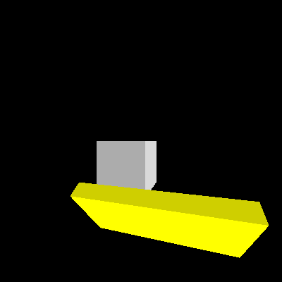
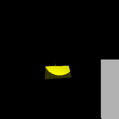
With luck, the new beam will appear about the same width to the eye as the old one:
Good enough. The image looks better without the massive performance strain of high subdivision levels.
Refactoring Drawing
There’s still something not right, but it will take a few more objects in the scene to show it. draw_view is already a repetitive hardcoded mess and it’s been on the “to be refactored” list for a while, so now seems a good time to clean it up before I add to the mess.
draw_view performs a series of transformations and state settings for each object drawn. I want to move to a more data-driven design, with each object in the simulated world represented by a data structure specifying the needed transformations and settings. Eventually, these structures may become full-fledged blessed objects, but I’ll start simple for now.
I initialized the data structures in init_objects:
sub init_objects
{
    my $self = shift;

    my @objects = (
        {
            draw        => \&draw_axes,
        },
        {
            lit         => 1,
            color       => [ 1, 1,  1],
            position    => [12, 0, -4],
            scale       => [ 2, 2,  2],
            draw        => \&draw_cube,
        },
        {
            lit         => 1,
            color       => [ 1, 1, 0],
            position    => [ 4, 0, 0],
            orientation => [40, 0, 0, 1],
            scale       => [.2, 1, 2],
            draw        => \&draw_cube,
        },
    );

    $self->{world}{objects} = \@objects;
}
Each hash includes the arguments to the various transformations to apply to it, along with a reference to the routine that actually draws the object and a flag indicating whether the object should be subject to OpenGL lighting. The object array then becomes a new part of the world hash for easy access later.
I called this routine at the end of init as usual:
$self->init_objects;
I also replaced draw_view with a version that interprets the data into a series of OpenGL calls:
sub draw_view
{
    my $self    = shift;

    my $objects = $self->{world}{objects};

    foreach my $o (@$objects) {
        $o->{lit} ? glEnable (GL_LIGHTING)
                  : glDisable(GL_LIGHTING);

        glColor(@{$o->{color}})        if $o->{color};

        glPushMatrix;

        glTranslate(@{$o->{position}}) if $o->{position};
        glRotate(@{$o->{orientation}}) if $o->{orientation};
        glScale(@{$o->{scale}})        if $o->{scale};

        $o->{draw}->();

        glPopMatrix;
    }
}
The new routine iterates over the world object array, performing each requested operation. It either skips or defaults any unspecified values. First up is the choice to enable or disable GL_LIGHTING, followed by setting the current color if requested. The code next checks for and applies the usual transformations and finally, calls the object draw routine.
For simplicity and robustness, I’ve unconditionally wrapped the transformations and draw routine in a matrix push/pop pair rather than trying to detect whether they need the push and pop. OpenGL implementations tend to be highly optimized with native code, and any detection I did would be Perl. Chances are good that such an “optimization” would instead slow things down. This way, my code stays cleaner and even a misbehaving draw routine that performed transformations internally without cleaning up afterwards will not affect the next object drawn.
A quick test showed that this refactored version still worked. Now I could add a few more objects to demonstrate the remaining lighting issue. I specified several more boxes programmatically by inserting a new loop before the end of init_objects:
    foreach my $num (1 .. 5) {
        my $scale =   $num * $num / 15;
        my $pos   = - $num * 2;
        push @objects, {
            lit         => 1,
            color       => [ 1, 1,  1],
            position    => [$pos, 2.5, 0],
            orientation => [30, 1, 0, 0],
            scale       => [1, 1, $scale],
            draw        => \&draw_cube,
        };
    }

    $self->{world}{objects} = \@objects;
}
For each box, just two parameters vary: position and Z scale. I chose the position to set each box next to the last, progressing along the -X axis. The scale is set so that the height and width of each box remains the same, but the depths vary from very shallow for the first box to fairly deep for the last.
The loop specifies five boxes in total and begins by calculating the X position and Z scaling (depth) for the current box. The next few lines simply create a new hash for the new box and push it onto the object array.
Finally, there was one last change–the bright world light overwhelms the problematic effect from the flashlight. This is an easy fix; I commented out the line that enables it:
sub set_world_lights
{
    glLight(GL_LIGHT0, GL_POSITION, 0.0, 0.0, 1.0, 0.0);

#     glEnable(GL_LIGHT0);
}
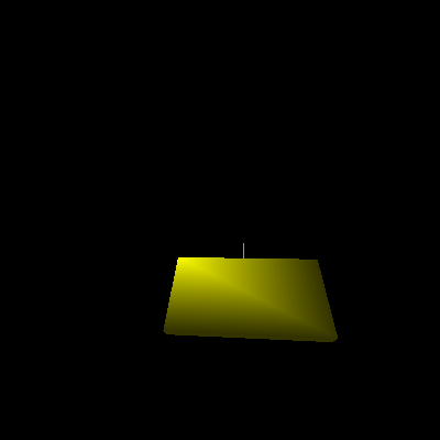
By panning to the left across the scene until the viewpoint is in front of the new boxes, the problem becomes obvious:
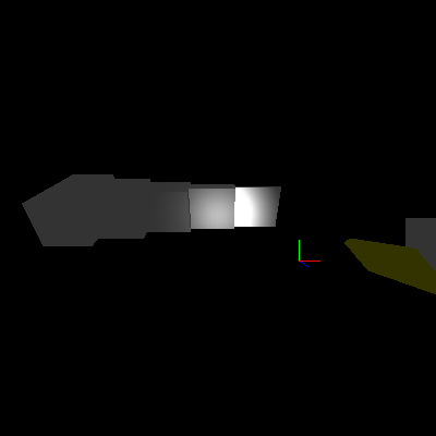
The brightness of the lighting varies immensely depending on the depth of the box! This rather unintuitive outcome is an unfortunate side effect of how OpenGL must handle normals. A normal specifies the direction of the surface associated with a vertex. If a rigid object rotates, its surfaces rotate, so all of its normals must rotate as well. OpenGL handles this by transforming normal coordinates as it would vertex coordinates. This runs into trouble with any transformations other than translation and rotation. OpenGL calculations assume that normals are normalized (have unit length). Scaling the normal breaks this assumption and results in the effect seen above.
To fix this, I told OpenGL that normals may not have unit length and that OpenGL must normalize them before other calculations are performed. This is not the default behavior because of the performance cost of normalizing each vector. An application that can ensure normals are always unit length after transformation can keep the default and run a little faster. I want to allow arbitrary scaling of objects, so I enabled automatic normalization with another line at the end of prep_frame:
glEnable(GL_NORMALIZE);
That fixed the problem:
With that bug killed, I reenabled the world light by uncommenting the glEnable line in set_world_lights:
sub set_world_lights
{
    glLight(GL_LIGHT0, GL_POSITION, 0.0, 0.0, 1.0, 0.0);

    glEnable(GL_LIGHT0);
}
Conclusion
During this article I’ve moved pretty quickly, covering screenshots, movement of the viewpoint, the beginnings of lighting in OpenGL, and subdivided faces for the boxes. Along the way, I took the chance to refactor draw_view into a more data-driven design and made the scene a little more interesting.
Unfortunately, these new changes have slowed things down quite a bit. OpenGL has several features that can improve performance considerably. Next time, I’ll talk about one of the most powerful of these: display lists. I’ll also introduce basic font handling and run with the performance theme by adding an FPS display to the engine.
Until next time, have fun and keep hacking!
Tags
Feedback
Something wrong with this article? Help us out by opening an issue or pull request on GitHub
Site Map
License
This work is licensed under a Creative Commons Attribution-NonCommercial 3.0 Unported License.

Legal
Perl.com and the authors make no representations with respect to the accuracy or completeness of the contents of all work on this website and specifically disclaim all warranties, including without limitation warranties of fitness for a particular purpose. The information published on this website may not be suitable for every situation. All work on this website is provided with the understanding that Perl.com and the authors are not engaged in rendering professional services. Neither Perl.com nor the authors shall be liable for damages arising herefrom.